Wet surface air coolers
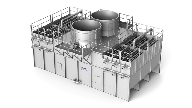
Alfa Laval Wet Surface Air Coolers (WSAC®) are custom built, closed-loop cooling and condensing systems that combine high performance, low operating costs, compact size and reliable operation. Renowned for their robust design and high efficiency, Alfa Laval WSACs are used in a large number of demanding industries. Their low water consumption and high cooling capacity have made them a popular choice in applications where low temperatures are required for process improvements.
Benefits
- Lowest possible process fluid outlet temperature thanks to evaporative cooling
- Minimal water consumption – cooling water can be re-circulated and the makeup water can be of low quality
- Low energy consumption
- Compact size and lowest lifecycle cost
- Well-proven technology and long service life
Alfa Laval WSAC systems are engineered-to-order, closed-loop cooling and condensing systems. Thanks to Alfa Laval’s WetSurface technology, these units provide maximum cooling in a compact unit and use a minimum of water and electric power. The robust and simple design brings stable thermal performance and low maintenance requirements. An Alfa Laval WSAC is a closed loop system, meaning there is no risk of contaminants entering the process stream.
Our WSAC systems can be fully customized to your requirements, for example they can be designed to withstand corrosive media, cool several process streams in parallel or with the ability to run in both dry-cooling and wet-cooling mode.
Find out more about our tailored air cooling solutions
Finding the right cooling solution for your industrial process can be quite challenging depending on many different factors. Water access is one of them - you may have limited or no access at all to water. You may also be struggling with seasonal changes and other challenges.
In this video you will find out more about our range of air-cooled heat exchangers and which cooling solution is ideal for you based on your specific requirements.
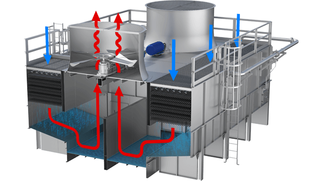
How it works
Watch videos and animations to learn more about the working principle of wet surface air coolers.
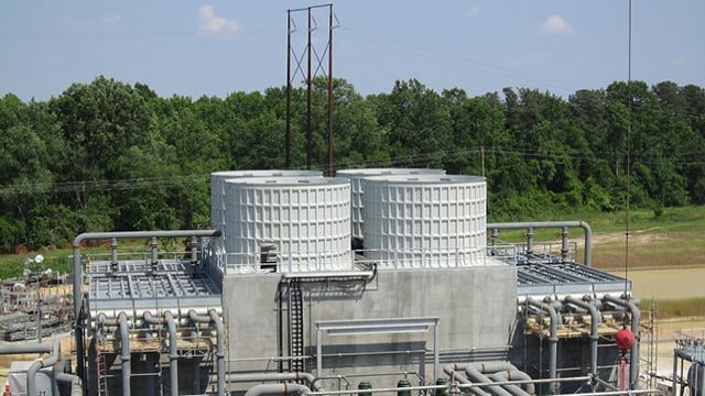
WSAC systems
WSAC systems come in all sizes from small, packaged units to large field-erected systems. Find out more details about the different systems.
FAQs
Find answers to the most frequently asked questions when it comes to wet surface air coolers.
Unique features
Alfa Laval Energy news on Linkedin
Learn how our solutions, and the support we can offer, can help you identify new possibilities for both profitable growth and a positive environmental impact. On our showcase page you can keep up to date with our latest innovations and solutions and the work we do within clean energy, energy efficiency, and the circular economy.

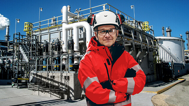
Accelerating sustainable solutions
Imagine a more sustainable world. A world in which less is needed to produce even more. A world in which we efficiently meet our growing energy needs and at the same time reduce CO2 emissions. Imagine a world where we can harness the power of natural resources while preserving them. At Alfa Laval, we don't just imagine this world. We build it together with our customers and our partners.